How to Calculate and Select Speed, Thrust, and Load Parameters of an Electric Cylinder for Stamping Machinery
1. Introduction: Why Electric Cylinders Are Replacing Hydraulic Actuators in Stamping Machinery
For decades, the hydraulic actuator was the default choice for stamping and press-fit machinery because it could deliver enormous static thrust in a compact package. Today, however, the electric cylinder — a fully electromechanical device that converts rotary servo motor motion into linear motion through a precision ball screw or roller screw — has emerged as a serious alternative. A modern linear motor actuator or linear electric motor driven press offers programmable force-position-speed profiles, energy savings of 30–60%, zero hydraulic oil leaks, and dramatically better repeatability.
The critical question for mechanical and design engineers is no longer “hydraulic or electric?” but rather: “Which electric cylinder specifications do I actually need?” Selecting the wrong thrust rating, stroke speed, or screw lead can result in undersized equipment that stalls mid-stroke, or oversized equipment that wastes money and cycle time. This guide explains, step by step, how to calculate and select the key parameters — speed, thrust force, load capacity, and duty cycle — when applying an electric cylinder to stamping machinery.
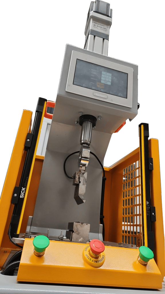
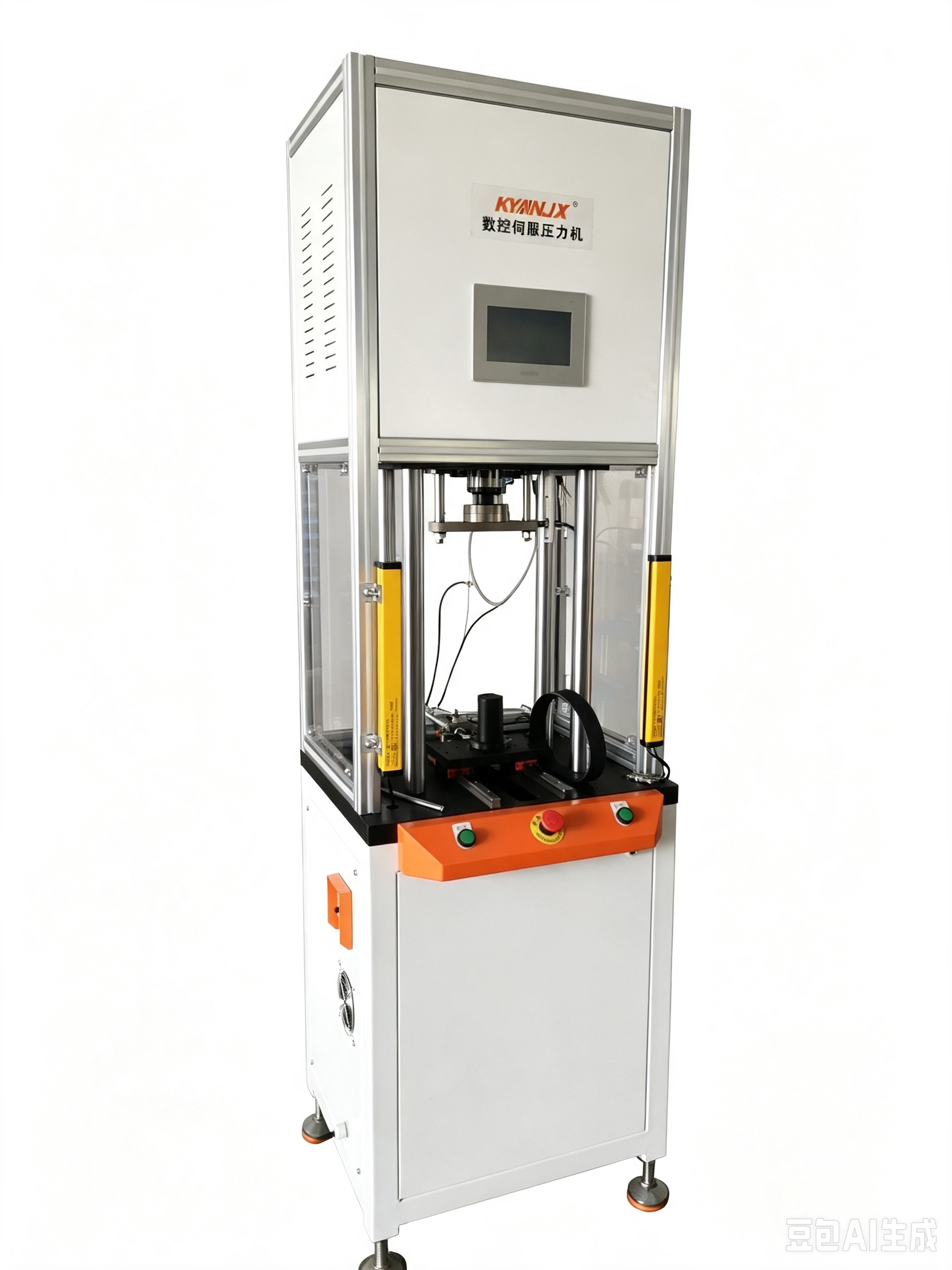
Fig. 1 — A servo press driven by an electric cylinder replaces the traditional hydraulic power pack entirely.
2. The Five Key Parameters You Must Define First
Before any calculation begins, collect the following data from your stamping process:
- Required press force (tonnage) at the working point — from blanking, piercing, drawing, or press-fit requirements
- Working stroke (fast approach, pressing, dwell, return) and total travel
- Required cycle time (strokes per minute, SPM)
- Load direction — pure axial thrust, or thrust combined with side (moment) loads?
- Environment — duty cycle, temperature, contamination, required life in cycles
2.1 Step One: Calculating the Required Thrust (Push/Pull) Force
The electric cylinder must produce enough linear force to complete the stamping operation. The basic equation is:
F_required = F_process + F_friction + F_gravity + F_reserve
Where:
- F_process — the forming or blanking force. For blanking/piercing: F_process = P × t × τ, where P is the perimeter of the cut contour (mm), t is material thickness (mm), and τ is the material shear strength (N/mm²). For press-fitting: F_process ≈ π × d × L × p × μ (shaft diameter, contact length, interference pressure, friction coefficient).
- F_friction — guide and seal friction, typically 5–10% of the process force.
- F_gravity — only for vertically mounted cylinders: F_g = m × g.
- F_reserve — a safety margin of at least 25–50% above the sum, to absorb material variations, tool wear, and shock peaks.

Fig. 2 — Force balance on the load: process force plus friction must both be overcome by the cylinder.
Worked example: A stamping die must blank a 200 mm perimeter contour in 2 mm mild steel (τ ≈ 340 N/mm²). F_process = 200 × 2 × 340 = 136,000 N ≈ 136 kN ≈ 13.9 tons. Adding 10% friction (13.6 kN) and a 40% safety reserve: F_required = (136 + 13.6) × 1.4 ≈ 209 kN ≈ 21.3 tons. You would therefore select a heavy-duty electric cylinder rated at least 25 tons, not the “20-ton” class, because catalog ratings are usually peak values, not continuous.
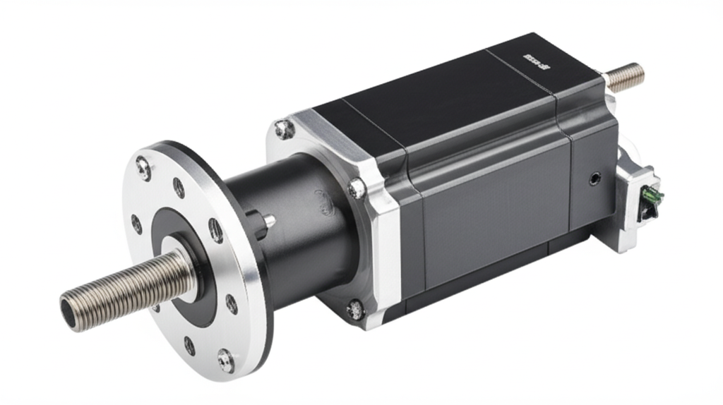
Fig. 3 — Heavy-duty electric cylinders in the 20–50 ton class are now standard equipment for servo stamping presses.
2.2 Step Two: Calculating Speed and Cycle Time
Stamping productivity is defined by strokes per minute (SPM). The electric cylinder must traverse its stroke within the available time budget:
t_total = t_fast_approach + t_pressing + t_dwell + t_return ≤ 60 / SPM
Each phase has its own speed limit. Fast approach and return speeds are limited by the motor maximum speed (typically 3,000–5,000 rpm for servo motors) and the screw lead:
v = n × L_lead / 60 × η_v
where v is linear speed (mm/s), n is motor speed (rpm), L_lead is the screw lead (mm/rev), and η_v (≈ 0.9) accounts for transmission losses. For a 10 mm lead screw at 3,000 rpm: v ≈ 3000 × 10 / 60 × 0.9 = 450 mm/s.
The pressing (working) speed is different: it is limited by force, not by motor rpm. Under load, available speed drops roughly along the servo’s constant-power curve:
v_press ≈ P_motor × η / F_required
For example, a 5.5 kW servo with η = 0.85 producing 209 kN gives v_press ≈ 5500 × 0.85 / 209000 ≈ 22 mm/s. If the stamping operation needs 30 mm of pressing travel, the pressing phase takes 30 / 22 ≈ 1.36 s. A C-frame servo press using a linear electric motor or roller-screw electric cylinder can typically achieve 15–40 SPM depending on stroke length — competitive with many hydraulic presses and far more controllable.
Fig. 4 — Commercial electric servo presses: the linear electric motor and electric cylinder combination delivers programmable speed and force at every point of the stroke.
2.3 Step Three: Verifying Load Capacity, Moment Loads, and Buckling
An electric cylinder is not only a force device — the rod and its support bearings must survive the way the load is applied. Three checks are mandatory:
- Buckling: a long, slender rod under compression can buckle before it reaches its rated force. Manufacturers provide force-vs.-stroke buckling curves; never exceed them at your installed stroke.
- Moment loads: if the stamping tool imposes any side force or offset center of gravity, pitching, yawing, and rolling moments appear (Fig. 5). The combined moment criterion must satisfy |Mp|/Mpmax + |My|/Mymax + |Mr|/Mrmax ≤ 1.
- Side-thrust from eccentric dies: keep eccentricity below the catalog limit, or add external linear guides so the cylinder carries only pure axial load.
Fig. 5 — Moment load directions on a linear motor actuator depend on installation orientation.
Fig. 6 — Worked moment calculation example from a linear actuator engineering handbook.
2.4 Step Four: Motor Power and Duty-Cycle Verification
Peak force alone does not size the motor — average power and thermal load do. For a duty cycle D = t_work / t_cycle:
P_avg = (F_press × v_press × t_press + F_idle × v_fast × (t_approach + t_return)) / t_cycle / η
Check the result against the servo’s rated torque at the required rpm, and verify that the RMS (root-mean-square) torque over the full cycle does not exceed the motor’s continuous rating. Stamping is a high-duty application: choose an electric cylinder with a roller screw if the machine runs multiple shifts, because ball screws wear out quickly under repeated heavy shock loads.
3. Electric Cylinder vs. Hydraulic Actuator: A Quick Comparison for Stamping
表格
| Parameter | Hydraulic Actuator | Electric Cylinder | Impact on Stamping |
|---|---|---|---|
| Force control | ±2–5% typical | ±0.5–1% with load cell | Better part quality, less scrap |
| Speed profile | Valve-limited, fixed | Fully programmable, any curve | Soft-touch, forming at any speed |
| Energy | Idling pump losses | Consumes power only when moving | 30–60% energy saving |
| Environment | Oil leaks, noise | Clean, quiet (<70 dB) | Suitable for cleanrooms |
| Maintenance | Seals, oil, valves | Lubrication of screw only | Lower lifetime cost |
| Peak force density | Very high | High (roller screw) | Covers most stamping tonnages |
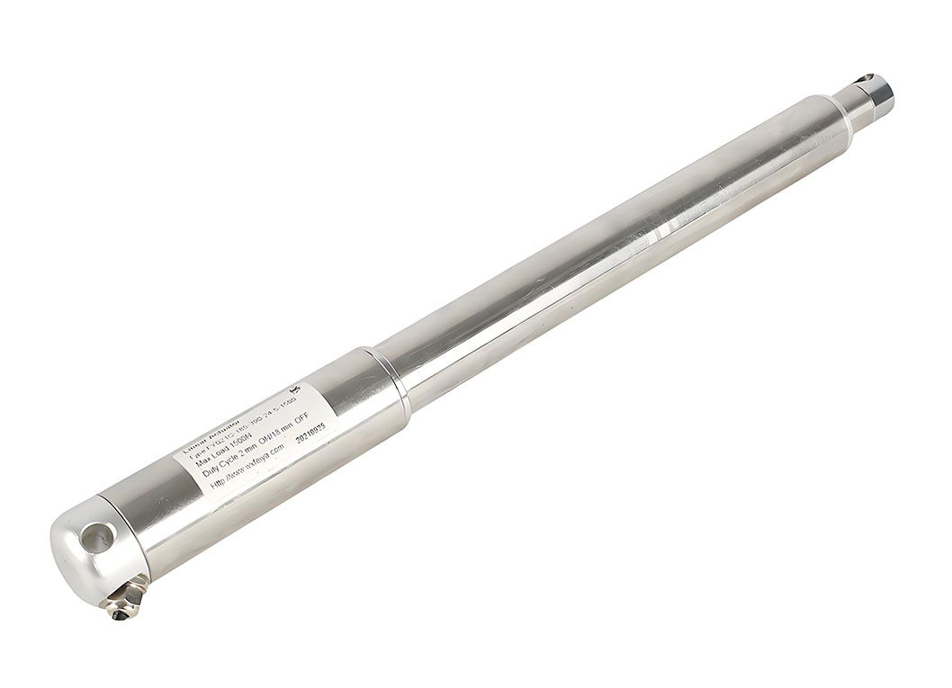
Fig. 7 — Extreme-force electric press actuators rated for continuous-duty stamping applications.
4. Conclusion: A Systematic Selection Workflow
Selecting an electric cylinder for stamping machinery is an engineering calculation, not a catalog guess. Follow this five-step workflow:
- Compute the process force from material and contour data, then add friction, gravity, and a 40% reserve;
- Break the cycle into approach, press, dwell, and return phases and verify each against motor speed and the constant-power curve;
- Check buckling, moment loads, and eccentricity at full stroke;
- Verify RMS torque, average power, and thermal duty;
- Choose a roller-screw linear motor actuator rated one frame size above the bare minimum.
Engineers who run these numbers find that a linear electric motor driven electric cylinder can replace most hydraulic actuator stamping stations below ~100 tons, while delivering programmable quality, lower energy bills, and a cleaner factory floor. Whether you are retrofitting an old press or specifying a new servo stamping line, treat speed, thrust, and load calculations as the foundation of a reliable, profitable machine.